Printables.com
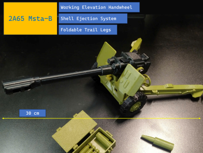
2A65 Msta-B (miniature artillery)
🏭 100+ tiskáren
·
po celé ČR
·
⏱ platba po přijetí tiskárnou
Autor modelu: Việt Phan Xuân
·
originál na Printables.com
Popis
Youtube video here:https://youtube.com/shorts/lemiBEvBD6U?feature=share
Supports and a brim are required. Z-hop may also be needed if your prints tend to get knocked off the bed.
If the print file has any issues, please let me know.
2A65 Msta-B - ASSEMBLY GUIDE
1. Cartridge Case Section
Assemble the two components as shown in the illustration.
Prepare a short spring and secure it in place using glue.
Note: Glue alone may not hold the spring securely over time. Use a small strip of paper, insert it into the tail end of the spring, and fix it in place as shown.
Use a piece of filament to attach the spring assembly to the rear of the cartridge case.
Apply glue to secure the rear component to the cartridge case.
Insert a shell to test whether the mechanism functions properly.
2. Frame Section
Assemble the hinge components onto the main frame, and use glue to secure them in place.
Assemble the wheels as shown in the illustration, and apply glue to fix the two halves of each wheel together.
Note: Do not attach the wheels to the frame at this stage, as they may interfere with the installation of the gear components.
Install the two trail leg hinges onto the main frame.
Note: Carefully observe the orientation of the hinges to avoid incorrect installation. Ensure that the recessed side of each hinge is facing outward, as shown in the illustration.
Apply glue to firmly secure the hinge components in place.
Attach the two trail legs and use pins to secure them in position.
The recessed feature on the hinges is designed to lock the trail legs in the deployed position. Open and fold the legs several times to ensure smooth and stable operation.
3. Elevation System (Gear Assembly)
Attach the handle grip to the handwheel, using a short piece of filament as a pin, and secure it with glue.
Connect the handwheel to the worm gear.
Note: The shafts are chamfered to ensure a proper fit. Pay close attention to their orientation when connecting them.
Install the next two gear components as shown in the illustration.
Rotate the handwheel to test the gear system, while simultaneously guiding the gear rack into position.
4. Breech Section
Assemble the three components as shown, using short pieces of filament as pins.
Note: You may need to use a drill or file to slightly widen the holes. Ensure that all parts move freely and are not tight or jammed.
Install the assembled unit onto the barrel body, using a piece of filament as a pin.
Secure the assembly in place using the top cover, as shown in the illustration.
Note: The top cover must be firmly glued, as it functions as a handle to pull the entire shell ejection mechanism.
Insert a shell fully into the rear of the barrel body, while simultaneously inserting the barrel from the front to determine its correct position. Once aligned, apply glue to secure the barrel.
While the glue is curing, insert the barrel assembly into the gun mount body, and allow it to set.
Ensure that this component can slide back and forth smoothly, as it serves as the shell ejection mechanism.
Note: The gray component must be oriented as shown in the following illustration.
Attach the muzzle component to the barrel and align it properly.
Then, install the gun mount assembly onto the main frame and secure it with two pins, as shown.
Finally, use a piece of filament to connect the gun mount assembly to the gear rack, linking it to the gear system.
5. Final Assembly
Attach the two wheels and the shield to the main frame to complete the assembly.
GOOD LUCK!
Podobné modely